
|
Product Details:
Payment & Shipping Terms:
|
| Pcb Size: | 80*330mm~1200*330mm | Pcb Clamp;ing: | Adjustable Pressure Pneumatic |
|---|---|---|---|
| System: | Windows7 | Software: | R&d Independently |
| Display: | Touch Screen Monitor | Input Device: | Keyboard,mouse |
| No. Of Camera: | 6 | POWER: | 380AC 50HZ |
| Power Consmption: | 5kw | Mounting Mode: | Group To Take And Group To Mount |
| Components Space: | 0.2mm | Feeders Stations: | 68PCS |
| Nozzles: | 34PCS | Mounting Speed: | 150000CPH~`80000cph |
| Mounting Height: | 13mm |
1.product details
Components of this high speed SMT mounter machine ht-f7 can mount include LED3014/3020/3528/5050 and resistor,capacitors,bridge rectifiers,etc.
![]()
2.product Technical parameters of high speed pick and place machine
| Model number | HT-F7 |
| Dimension | 2700*2120*1550mm |
| PCB size | 80*330~1200*330mm |
| PCB thickness | 0.5~5mm |
| PCB clamping | adjustable pressure pneumatic |
| mounting mode | group to take and group to mount |
| system | windows 7 |
| display | touch screen monitor |
| input device | keyboard,mouse |
| NO.of camera | 5 sets of imported camera |
| mounting precision | ±0.02mm |
| mounting height | <13mm |
| mounting speed | 200000CPH |
| components space | 0.2mm |
| NO.of feedings station | 68pcs |
| NO.of nozzles | 34pcs |
| power | 380AC 50HZ |
| power consumption | 6KW |
| operating environment | 23℃±3℃ |
| conveyor transmission | MAX length:1200mm |
| transmission speed | >500mm/sec |
| transmission direction | single(left→right,right→left) |
| transmission mode | online drive |
| position mode | optical |
| air pressure | >5.0kg/c㎡ |
| electrical control | independent research and development by ETON |
| motion control card module 1set | independent research and development by ETON |
| X.Y axis drive way | high-end magnetic linear motor+servo motor |
| feeding way | electric feeder with double motor |
3.product features of smt pick and place machine
![]()
4.Packing & shipping of smt mounter machine
![]()
5.Company profile
![]()
![]()
![]()
![]()
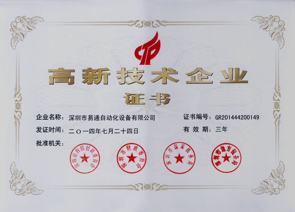
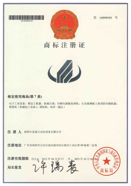
6.Our Our certificates and certifications
![]()
7.our services
![]()
8. trade show
![]()
![]()
Industry related knowledge
We will generally make MARK coordinates, and then through MARK identification to do component library, patch first identify MARK then patch; MARK identification after how to judge the MARK deviation, whether based on the identification results and then locate MARK center coordinates and program MARK coordinates comparison, get the deviation, and then act on the patch coordinates.
In motion, the placement alignment technique aligns:
When a new PCB to be mounted is transmitted to a designated location through a board feeding mechanism, the reference (MARK point) camera mounted on the patch head CCD3 the corresponding area is searched by image recognition algorithm, and its coordinates in the coordinate system are calculated by the system software, and the location data of the corresponding components should be pasted to the main control computer. When the corresponding mounting components are picked up and passed through the component camera, the camera detects the components, obtains their position coordinates after picking up and sends them to the main control computer, compares with the target position, obtains the position and rotation angle that the mounting head should move, and adjusts the position and rotation angle before sticking, so as to achieve the purpose of visual alignment.
contact
Name:Brynn
Email :Brynn@eton-mounter.com
WeChat:13802252825
Telephone:138 0225 2825
Contact Person: Ms. Linda
Tel: 0086 13670197725 (Whatsapp/Wechat)
Fax: 0086-755- 29502066
| Factory Address:HENGFENG INDUSTRIAL AREA,ZHOUSHI ROAD NO. 739,HEZHOU COMMUNITY,HANGCHENG STREET,BAOAN,SHENZHEN,CHINA | |
| Sales office:HENGFENG INDUSTRIAL AREA,ZHOUSHI ROAD NO. 739,HEZHOU COMMUNITY,HANGCHENG STREET,BAOAN,SHENZHEN,CHINA | |
| +0086-136-70197725 | |
| linda@eton-mounter.com | |